!!Attention!!
I changed the parts numbering. Same order but more numbers. Please don't be surprised that I start here with a higher part number.
Wings
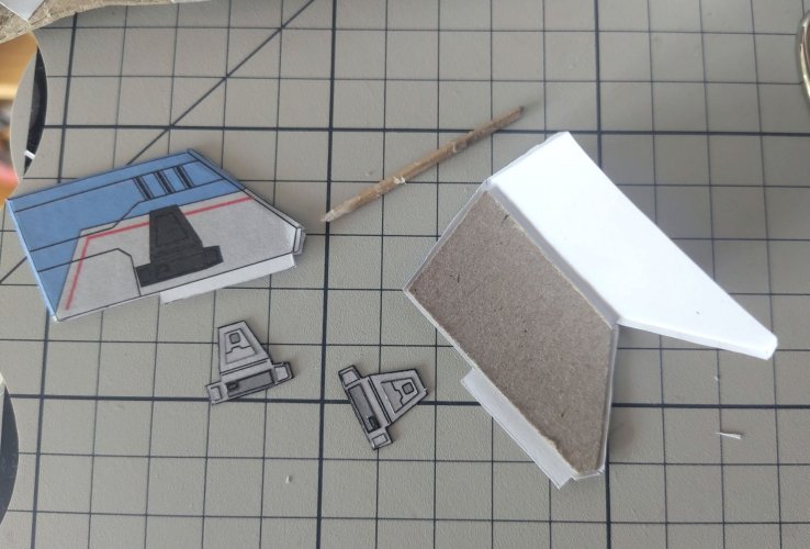
Cut out the lower wings, part 43/45, and the corresponding greeble parts 44/46.
Use 47 to prepare 1mm grey board that will go into the wings.
Glue the board to the inside of the wings, close the side tabs BUT leave the front tip of the wings open! You have to attach two antennas there later on.
Glue the assembled greeble parts onto the darkened out area. This will help you later when attaching the connection to the upper wings.
Apply normal glue to the white tabs and insert them into the slits you cut in the atmo engines.
The wings should stick out 2mm beyond the end of the tabs protruding from the atmo engines. Those orange/grey tabs pointing to the rear.
cut out 48 (top of upper wing), use 49 to laminate it to 0,5mm grey board. Shape the wing. The tip should point slightly upward by approximately 35°. The narrow grey face and the white glue tab on the other end should point down by 90°.
Cut out and fold part 51. It consists of three faces. Glue the grey irregular quadrilateral, the tip of the wing, to the underside of the upper wing. The narrow grey mid is the connection to the lower wing. Reinforce it with 0,5mm board using 52 as template. The blue face is the glue tab but first glue 53 to the underside.
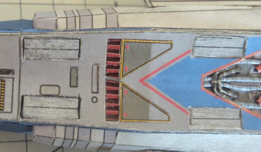
Now carefully cut a slit on each side of the top of the engine section on the hull, between the grey-blue tube and the red round tube/cable connector thing. The area for the slit is marked by a thick dark-grey line.
Apply some glue to the white tab on the upper wing and insert it into that slit. Don't confuse the sides! The wing tip should point forward!
Glue the blue tab of the upper wing connection onto the lower wing, on the corresponding area of same shape. The connecting grey face should sit right next to the greeble on the lower wing.
Repeat that procedure for the other side.
Airlock
Cut out 54 - 57. Roll up 55 as a ring, print facing inwards and 56&57 print facing outwards.
Glue 55 on top of the rim of 54, wider radius facing up, apply glue on that new rim and put 56 on top.
Orient the hatch window to a specific direction, turn the hatch around and glue 57 to the outer rim of 56 on the underside, making sure the hatch window is aligned with the cutaways in 57. Check from the other side and carefully make adjustments as long as the glue did not dry out.
Glue the hatch at the joint area of part 11&12, on top of the ship hull marked with a dotted circle.
The hatch parts come with a second spare set in case you mess it up or are not satisfied with the result. I needed it, because the parts are really small for that assembly.
final hull greeble and antennas
58&59 for the greeble on the hull sides. I would advise to laminate the parts to at least one thick paper layer. Cut and glue 58s to the paper you used for the print. Cut and glue 59s next to them on the paper. Cut them out, paint the white paper edges black and glue each 59 on a 58. Then glue each round thing on the corresponding texture of the ship hull.
Glue the 60s between them.
Antennas
For the antennas, roll up 61 along long axis for the pole and glue tight. 62 is both sides of the dish, cut out, shape (one print on convex one on concave side) and glue back on back.
Apply glue on the hole, stick dish on pole at about one third of the length.
Stick and glue the antennas into the open lower wing tips, close the sides around the poles, align the antennas with ship axis and lock that orientation in with careful application of super glue.
removeable landing legs
I discovered this method on Revell-Fan's Viper MK1. All praise to
@Revell-Fan!
In case you want them, cut a slit on the forward and backward end of each closed landing bay texture on the belly of the ship.
Cut out and shape 63s, the open landing gear bays.
Cut out and glue the 64s on the unprinted upper side. Fold the white tabs on each end up. These are the inserting tabs, to attach the landing gear to the model.
Cut out the 65 and the greeble parts for them. Laminate one side of each of the four legs to 1mm grey board, cut it out again, glue the other side of the leg to it and greeble the light grey parts.
Cut out 66s. Cut out 67s and glue them on the backsides of the 66s. Cut out and glue 68s on the corresponding texture of the feet. Glue the feet to the legs. Reinforce this connection with super glue for rough landings

Insert the landing gear bays into the slits you made. Adjust the slits with the blade carefully until the pieces fit in, are aligned with the long axis and do not come off too easily. If they do fall out easy you can fix this with careful application of super glue as a glaze on the inserting tabs, to make them a little bit thicker. Or glue thin paper to them to achieve the same effect. Always do the check.
!!If you used super glue for this, make sure it dried out completely
!!
You can note the position of each landing gear on the blank top side to not mix them up later.
Now attach all bays and apply some glue to the dark areas.
Put on the legs, do not mix up front legs and hind legs! The hind legs are about 1mm lower and extended with a smaller angle. And the hind legs have to point to the back! Adjust the position of each leg then carefully put the ship on a flat hard surface on its legs.
Now you will notice that the legs are inclined inwards because of the concave ship underside. Carefully slide the handle of your pincer or something comparable between them to let them point straight to the ground.
Let the glue dry out. Then reinforce with super glue to be prepared for even rougher landings.
Congrats!
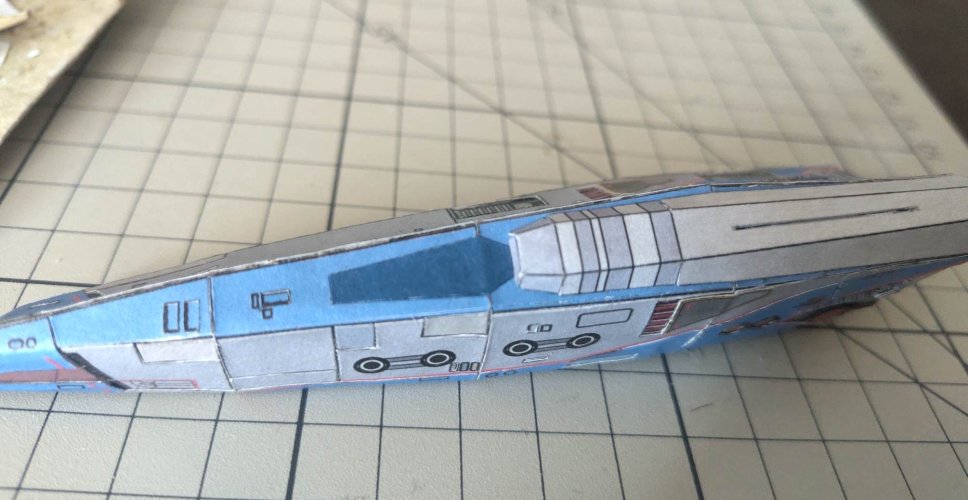
You are now a proud owner of the Teladi Kea (my paper interpretation of it; modified to a surface-orbit shuttle craft, small cargo hauler, personal yacht or fighter craft if you install some weapons on it)



)!
 why frightened?


 www.paperpapers.com