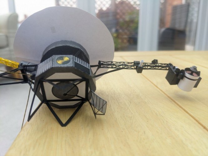
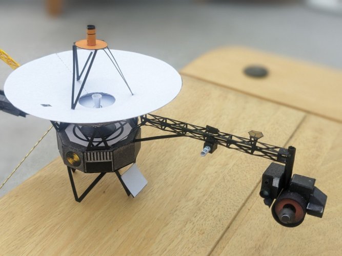
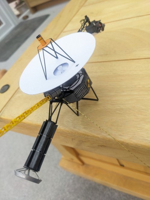
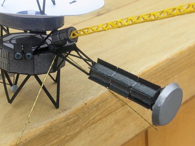
NASA Voyager 1/48 John Jogerst

Magnetometer (MAG) boom arm:
I've saved this till last ... you'll see why below!

There are 2 low-field magnetometers on the Voyager spacecraft. One is midway down the 13m (43 feet) arm and the other is at the far end. How did they get a 13m long boom stored and then deploy it on a compact payload in the 1970s? Another amazing feat of engineering. The arm is called an Astromast. "The Astromast is a fiberglass boom made of three longitudinal rods that run the length of the boom — thirteen meters, in Voyager's case. The rods are held in a triangular cross-section by fiberglass trusses and diagonal filament struts, all fastened with flexible joints. The entire boom is collapsed by twisting it and laying it in coils into a small canister — Voyager's was only about 70 centimetres in length. Deployment takes place in a controlled fashion by slowly letting out a central lanyard as the boom extends under the spring-force of its twisted fiberglass rods. The boom, and the instruments mounted to it, rotates as the boom deploys." https://www.quora.com/How-did-Voyagers-1-and-2-unfurl-so-to-speak-from-the-space-capsule This method of placing instruments away from spacecraft has been used on a number of other craft too, before Voyager and since.

The article quotes the above from a book, Deep Space Craft by Dave Doody (a NASA Engineer, amongst other things he worked on the Voyager programme). The page explaining the Astromast technology, including a photograph of the mast stored before deployment on Galileo, is available thanks to Google Books on p176 here https://books.google.co.uk/books?re...VUC&q=astromast#v=snippet&q=astromast&f=false There's a lot wrong with the internet and how it's used in the world today, but it's also an incredible knowledge-base and rich resource for those researching facts like these.

Here's a video of the later Europa Clipper magnetometer boom deployment to see how it works in practice

MAG Boom Greebling - making a "skeletal" hollow structure like the instrument truss
Here's a photo of the finished model from the instructions pdf showing the MAG boom - as it's quite narrow I can see why it's been done this way, folding a 25cm triangle with sides of less than 4mm is hard enough ...
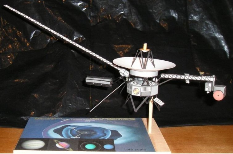
Voyager Finished Model From Instructions sm.jpg

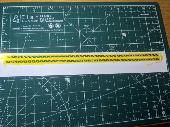
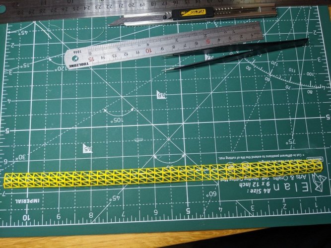
But then I did manage to do something with the instrument arm didn't I ... ok, I'll have a go at doing the same! I took the image and converted it from black to yellow in GIMP and printed a page on 300gsm card (for strength and stability at such a length) with a few copies of it.
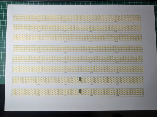
PXL_20250307_215851533 sm.jpg

I'll have a go and see if it's achievable. Wish me luck!

 
You have a great eye for details and thank you for the undepth information its very intresting to read.
 
  • Love
Reactions: Cyclops
This is indeed quite the build thread. The level of detail and greebling that you are putting into this project is AMAZING!
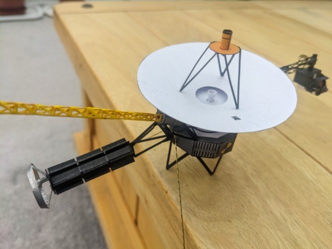
The inforation that you have found and are sharing with us is extrmely valuable and informative. So, thank you for that as well.
 
So, nearly there. But wait ... I feel the need for a little more greebling ...
Greebling 3: RTG enhancements
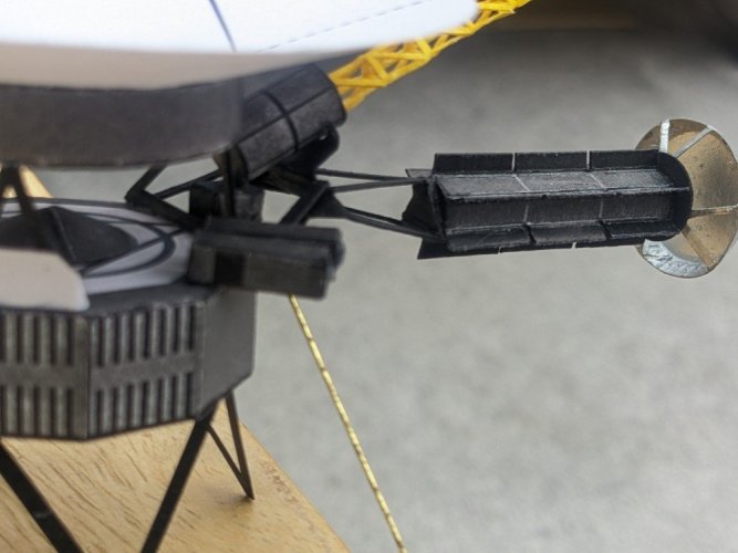
At the end of the RTG is that silver structure, I guess it's a protective shield or something. That looks doable :)
View attachment 224060

Cut some parts out (including a few strips in case I decided to attempt those legs as well).
View attachment 224061

A bit of trigonometry to figure out the inner radius needed to create the conical section round the flat end plate, and some struts. Here's partial assembly with a bit of bending in on the struts to glue onto the end of the RTG. All three struts folded in. The a quick layer of CA on the inside edges.
View attachment 224063

Then the whole thing gets a coat of silver paint.

I used a gloss silver enamel Humbrol paint I had from plastic kit modelling, which gave a really good uniform coverage on the inside and struts as you can see in the picture below, but on the outside I couldn't get it to spread uniformly flat with a brush, the brushstrokes stayed making it look a bit amateur, so after a couple of tries I resorted to a polished aluminium spray can, couple of coats and it's all looking ok.
View attachment 224064

Gluing it onto the RTG was a challenge - the main difficulty being I'm trying to glue a piece onto the main structure while getting it aligned in all 3 dimensions at once so that it's central to the RTG and the end plate is as close to 90º as I can make it. After three aborted attempts I rethought it.

I can't do it all at once. I need a way of splitting up the task, separating gluing it centrally to the RTG from also making it accurately perpendicular. So I cut out a circle and thought if I can put a bit of weight on top I can get the struts parallel to that circle, and then glue the circle to the RTG. So a bit of improvisation with Lego again, spotted some glue on the ends of the 3 legs, put the circle on top, then added the Lego on top of that to force the black circle to be parallel to the end plate itself. Also once the Lego was holding it down, I had a bit of time to be able to adjust the position of the circle to be as central to the end plate as possible.
View attachment 224065View attachment 224066
View attachment 224067View attachment 224068

Then it was simply a matter of gluing this to the RTG which was a lot easier to try and get it on centrally.
View attachment 224069

I have had my eye on those extra silver metal legs (where the RTG attached to the spacecraft before deployment where it hinged outwards) and the truss carrying cables across the top, and I would then think I have to make the whole of that RTG truss silver along with the MAG canister and who knows where this might end! But I need to find a finish line for this model soon, so for now I'll leave these extra opportunities. I might come back to them after I've made a few different models.
View attachment 224071
i love the gluing jig
 
  • Like
Reactions: Cyclops
Sorry for such a gap between posts. This final piece of the puzzle did take a lot of time complete, amongst other things going on in life (as happens to us all).

So I'm going to do a few posts to explain how my attempt at making an improved MAG boom arm went over the next couple of days. Starting with the thinking and planning of approach. I think this illustrates some of the issues working with card especially at very small scale.

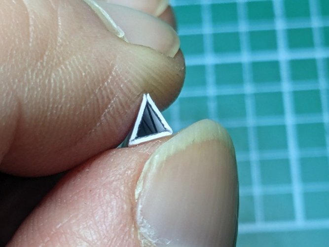
So I'm basically trying to create a 25cm long, just under 4mm per side wide, equilateral triangle. From my experience with the 4 sided instrument boom I had planned a slightly different approach. When doing in the instrument boom, because the long edges were very narrow (less than 1mm wide), it was very difficult to get them to fold along the centre of the edge evenly, and most of time, the longitudinal pieces resisted, and all that happened was that the latticework, where it met the long edge, bent there, which I'd prefer to avoid.

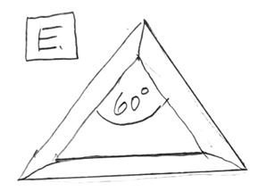
The question is, how to create reasonably sharp angles of only 60º, which means bending the card 120º back on itself. My first thought was to cut the 3 sides out individually, somehow sand or remove some of the material at the edges so that they don't end up looking like this when glued together.
1748467050217.png

And then somehow glue them along their length back together again. This would allow me to cut much wider edges, going outside the template and perhaps making it stronger.

However, the thought of trying to glue down the 25cm length of these 4mm wide "slices" didn't fill me with much joy, especially as I'd have to rig up some sort of jig to do it on, which has the equilateral triangle shape so that I got the angle right (and straight) all the way down. No easy task.

So I had a rethink, based on trying to keep it all as a single piece with folds. So it went like this ...

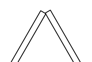
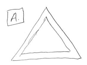
This is what I'm trying to achieve in cross-section:
PXM A.jpg

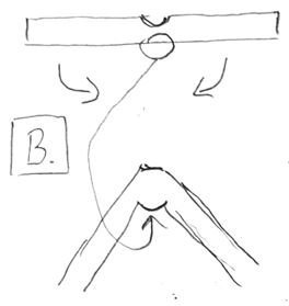
I have used a scoring/embossing tool on the project, which compresses the card to some extent (below top), but when scoring on the printed side, and then folding down, the material on the inside face just gets squashed and compresses into a bulge, which makes it difficult to get the acute angle I need.
PXM B.JPG

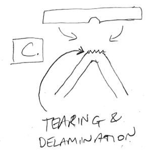
Next thought: mark through the card and score on the underside. Which works better, but I've also seen tearing and delamination on the top surface as a result of the acute angle bend.
PXM C.JPG


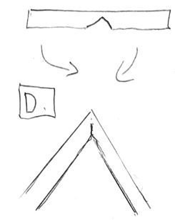
Next thought: could I cut out some of the material, leaving a little left at the deepest cut point, and then bend the two sides down?
PXM D.JPG

This might work, achieving the completed triangle section below:
PXM E.JPG

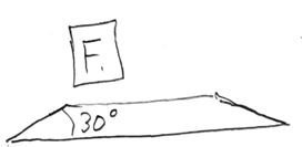
So in order to do this, I need to have approximately a 30º cut across the edge of each piece:

PXM F.JPG

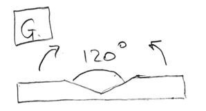
Keeping the 3 sides joined up but cutting out a shallow V shape in between the sections, this is what I'm aiming for, with a 120º angle across the cut. The two sides would then fold up into a 60º equilateral triangle shape:
PXM G.JPG

How could I achieve this, even roughly, along a 25cm length? I looked online for any sort of cutter that might help with this, as I need some sort of jig for my knife, to keep it at the right angle, and then to cut along a long length. I did find picture framer tools, but they only had set angles at 90º and 45º. Plus they were expensive.

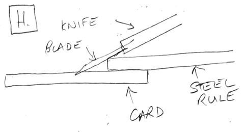
So I experimented a bit on a spare piece using the technique below, hold a steel rule in place and run the knife down into the card at a shallow angle and draw it along its length. This didn't work at all - it was difficult to even get to start a cut into the card, and I couldn't hold the angle at all.
PXM H.JPG

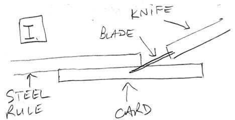
Then I thought, could I run the blade UNDER the steel rule from the opposite side. This worked much better on my experimental piece. The pressure of the steel rule made it easy to create a cut and it was easier to control the angle of the knife and the depth of the blade.
PXM I.JPG

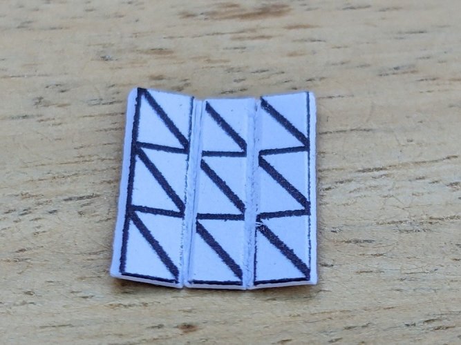
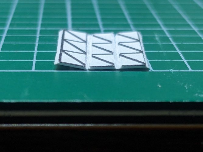
All this would have been easier to illustrate with a video, but my videoing skills aren't up to the job yet! Anyway, here are pictures of my very short experimental piece after trying with this technique:
PXL_20250330_153652747 sm.jpgPXL_20250331_173318764 sm.jpgPXL_20250331_173423204 sm.jpg

So this seems worth a go. Next time I'll show how I got on trying this on a 25cm long scale!
 
Lovely to see your thought process on the issue in hand - blade control is a tough art to master, I look forward to seeing how the finished part turns out
 
  • Like
Reactions: Cyclops
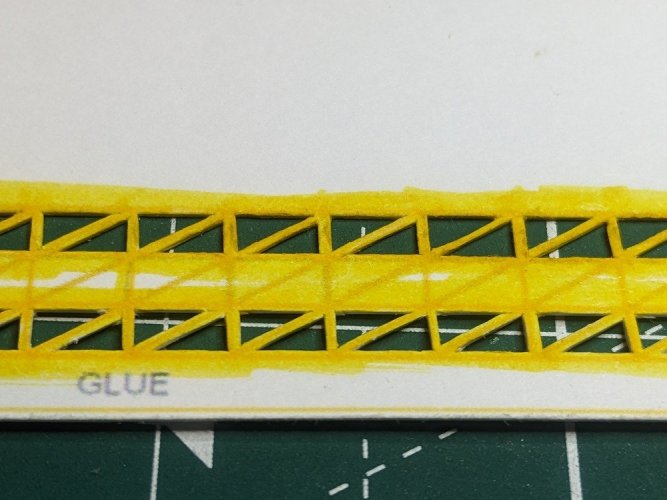
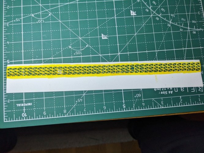
Here are 2 of the 3 sides cut out - lots of tiny triangles! This is where I paused because I was considering cutting these two strips out separately for my original plan. I'm glad I didn't.
PXL_20250323_172228297 sm.jpg
PXL_20250323_172254374 sm.jpg

Next job is to cut out the material on the inside two long lines and fold them before removing the triangles from the centre section, in order to help the folds (otherwise it will revert to wanting to bend where the latticework meets the edge pieces). Ideally I should have done this before removing any triangles at all, but I hadn't thought of this approach until I had got this far.

Also I thought about getting a piece of material, wood or plastic, with a 120º angle on it, that I could wrap or stick a bit of fine sandpaper to, that I could run up and down the ruts after cutting them roughly with the knife, just to encourage the full 120º angle before attempting to fold the sides inwards.

So using the "run the knife under the ruler" technique I had a go. One line turned out pretty good, the other not so much - I cut too deep and right through, splitting it in places. Some repairs required later on! Did a bit of fine grit sandpapering to smooth some of the inconsistent cutting. Overall not bad for a first attempt.
PXL_20250416_201413053 sm.jpg
PXL_20250416_211204559 sm.jpg

Then began shaping, trying to coax it to fold back on itself to create the triangular truss shape. Wondering if this was going to work at all ...
PXL_20250421_081934047 sm.jpg

Secured to the board so I could start running repairs and glue the outer edges together. Looks pretty rough to begin with, but as I went along things started to look better (I promise!).
PXL_20250423_151123665 sm.jpg

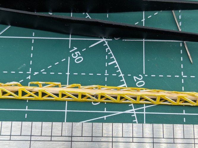
Cocktail sticks threaded up the centre made it easier to keep a straight shape along the length and provided a bit of support when gluing (I used the watery Starbond EM-02 for gluing this truss - for speed when going down the length and because it would receive a coating anyway at the end in order to give it strength not to bend when completed). Gluing along the 25cm length was difficult to achieve a perfect facing up of the two sides against each other ... I was doing the whole thing under my magnifying glass and I had no depth of field (more on this coming in my profile Intro soon), and I couldn't move the magnifying glass around to compare sides as I was applying the glue. I really needed 3 or 4 hands. I think a Headband Magnifying Glass would have helped here, instead of my big static one. Time to visit Amazon when this is completed!
PXL_20250503_113647682 sm.jpg

PXL_20250503_113703221 sm.jpg

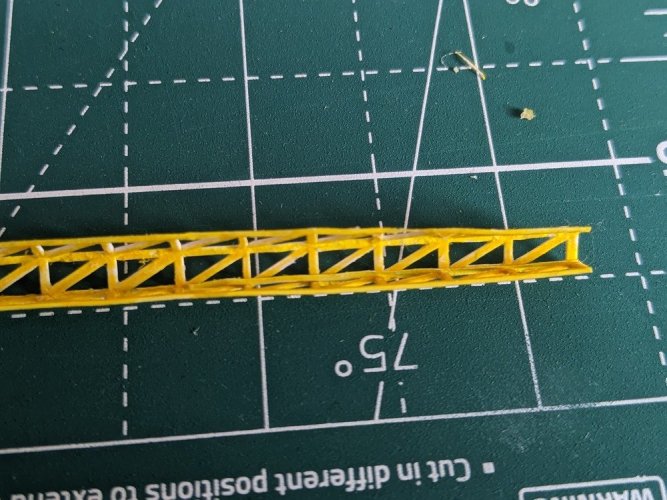
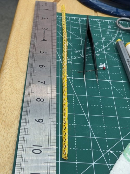
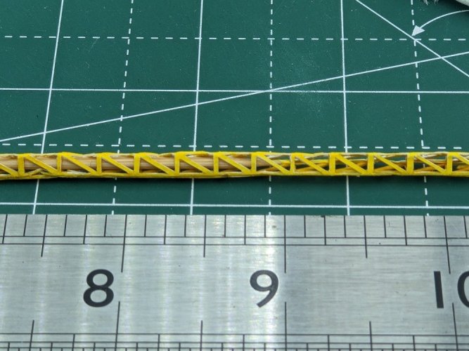
Coming along, patience and repeating "trust the process" under my breath a lot of times! Alongside all the repairs needed, I had to colour all the inner cut faces in the triangular sections yellow. 3 per triangle, 240 triangles, that's 720 surfaces to inspect, get the felt tip in there, check it's all covered etc. This is partly why it's been so long since I've posted. This took many hours to complete in short bursts over many sittings. Many times along the way I realised I should have tried sourcing a piece of yellow card so I didn't have to do all that colouring.

As I went along working on all the fine tuning and gluing into the triangular shape, it naturally became straighter along its length, and I didn't have to do much at all in the end to make it as straight as possible.
PXL_20250503_113807218 sm.jpg

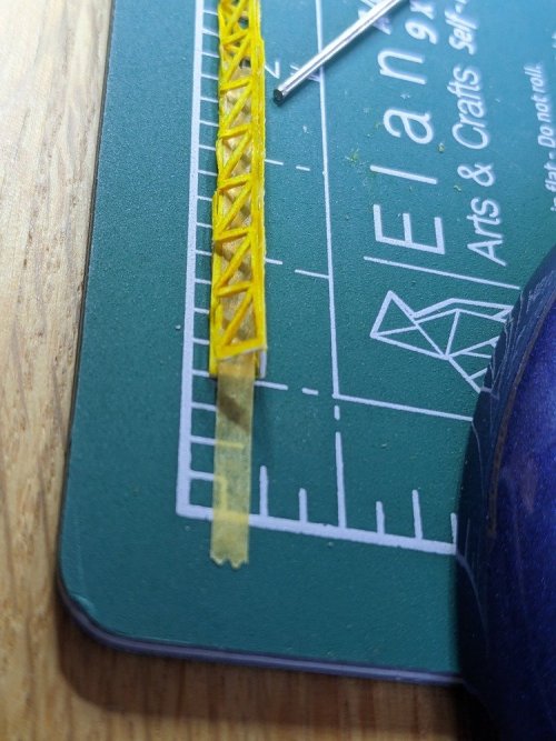
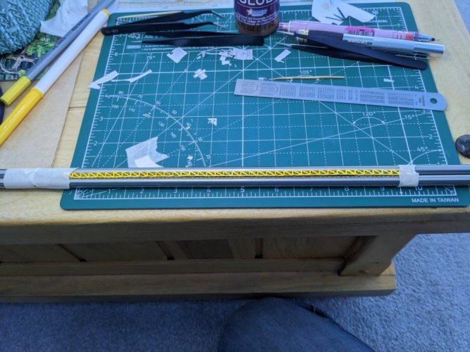
Once it was glued into the right shape most of the repairs were done while it was sitting in between a jig I made for it from a couple of dowels. Some were joining broken spurs back together, there were a couple of new inserts required, and some where the card was bent, where a bit of superglue when held straight sorted it out. It sits happily between these dowels, taped down at both ends, allowing me to perform surgery where required. Once finished, a brushing of EM-02 (other superglues are available) over all the surfaces gives it the rigidity it'll need to remain straight when in position in the model and under the influence of gravity.
PXL_20250509_184851659 sm.jpg

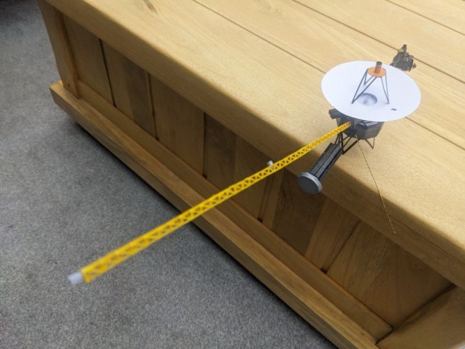
Overall I'm pretty pleased with how it turned out, especially for a first time.
 
Final greebling opportunity: Low Field Magnetometer instruments
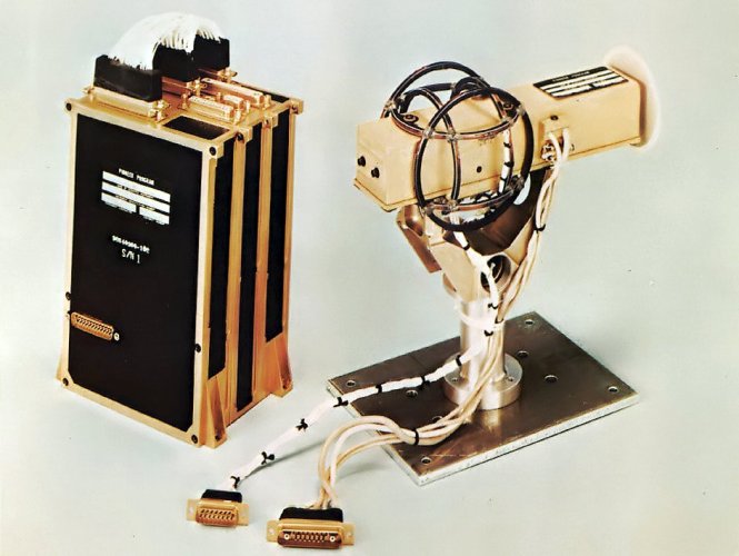
Once the boom was to a decent standard I moved on to the magnetometer instruments themselves. I couldn't find much information about the ones used specifically on Voyager, even fewer genuine photos - most seem to be stylised representations. This is from the earlier Pioneer spacecraft, basically just a rectangular box in shape.
Pioneer_10-11_-_P50_-_fx magnetometer.jpg

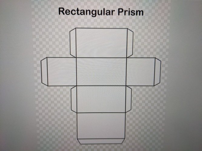
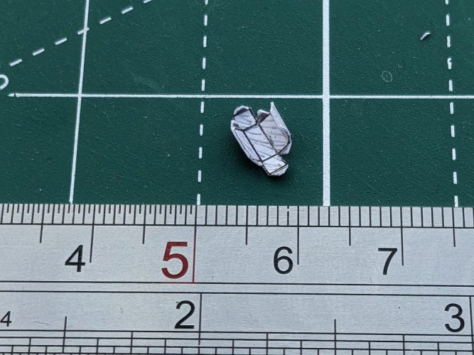
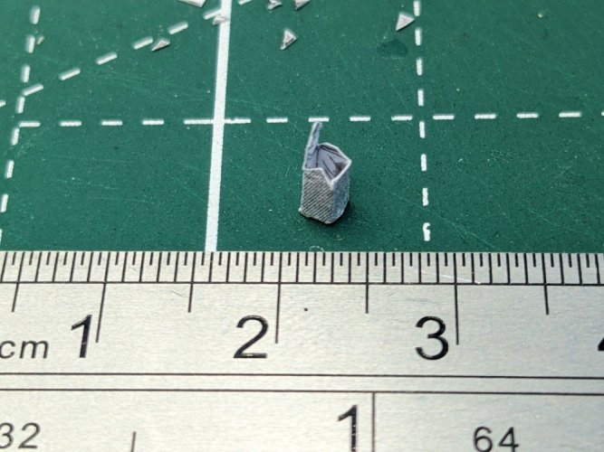
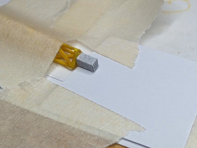
I did see a picture of what I think is the Voyager ones somewhere on the web but I can't find it again now and I didn't download or save it :( It was just a plain green/grey rectangular shaped instrument without the external things on the Pioneer one above, so I represented them that way, with scratch built rectangular prisms 4mm x 2mm x 2mm, rather than the flat "tabs" on JJ's model template. I printed these on 80gsm normal paper because they're so small that anything thicker would be too bulky to fold up into a box.
PXL_20250507_143439192 sm.jpgPXL_20250508_182049631 sm.jpgPXL_20250509_184625358 sm.jpg

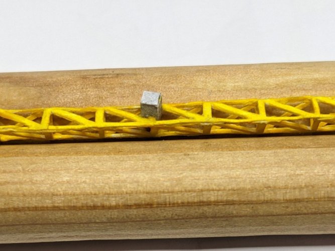
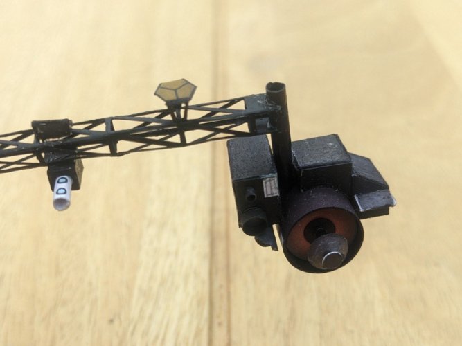
Here they're attached to the boom.
PXL_20250526_144823443 sm.jpg
PXL_20250526_151716572 sm.jpg

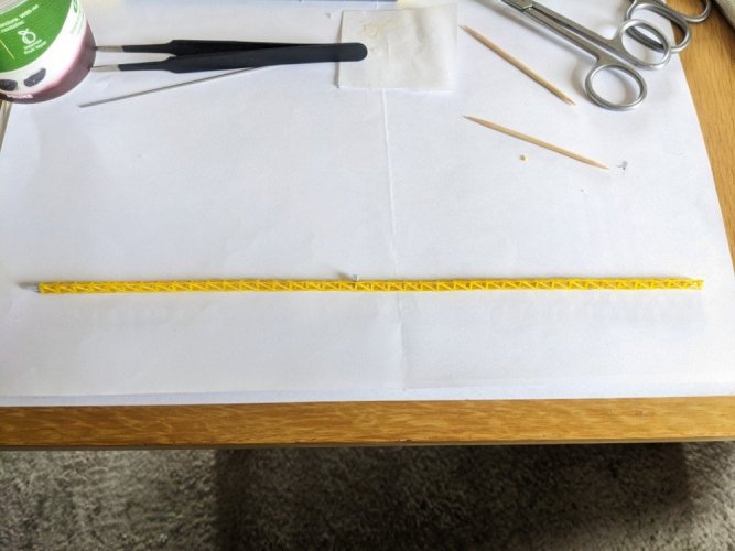
And the whole boom assembly before fitting into the MAG boom canister on the model. I think the one at the end is supposed to be sideways on instead of end on.
PXL_20250526_154020160 sm.jpg

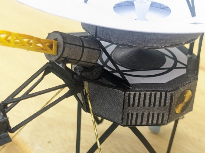
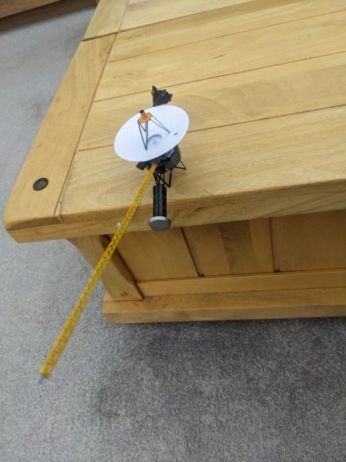
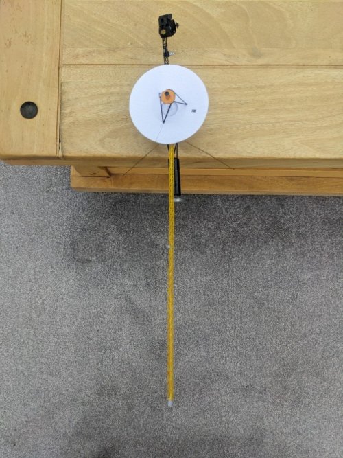
And finally here's the MAG boom assembly glued into the canister (achieved by getting some tacky glue into the far end of the cylinder with a cocktail stick, and then pushing the boom all the way to the back and stabilising while it dries).
PXL_20250527_120638783 sm.jpg